Fluxon Motor Fluxon Motor

What Is a Mini Gear Motor and How Does It Work?

Time:2026-09-13 Author:Charlotte
0%

A Mini Gear Motor is a compact motor-and-gearbox assembly that produces controlled rotary motion. It is common in small robots, camera mechanisms, medical instruments, toys, and automated valves. The motor spins quickly, but its gearbox reduces speed and increases usable torque. This trade-off makes precise movement possible inside a limited space. It is small, but not simple.

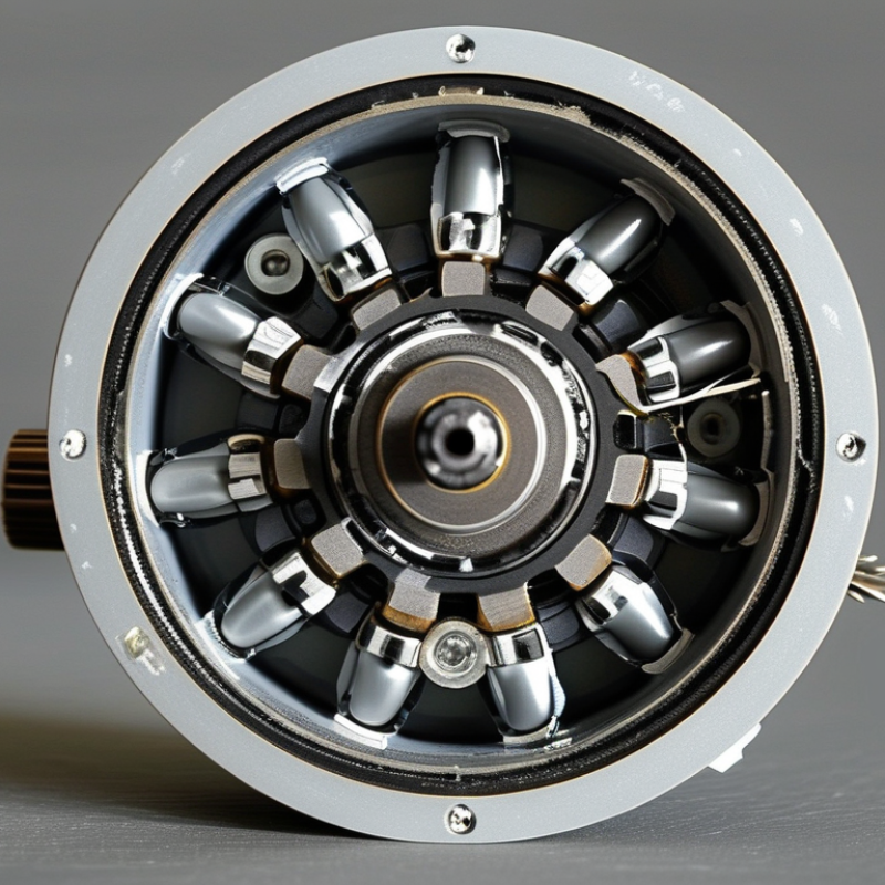
Inside the housing, electrical energy reaches a brushed or brushless motor. The motor creates magnetic force around a rotating shaft. That shaft drives several gears, often arranged in stages. Each stage changes speed, torque, and rotation direction. The output shaft then turns a wheel, lever, screw, or pulley. For example, a miniature conveyor may move slowly while the internal motor spins rapidly. Mechanical losses still occur. Heat, friction, and gear noise cannot be removed completely.

Selecting the right Mini Gear Motor requires more than checking its voltage. Engineers examine rated torque, stall torque, output speed, duty cycle, gear ratio, shaft size, and mounting pattern. A motor that works briefly may fail under continuous load. I have seen compact designs overlook starting current and gearbox backlash. That mistake can cause weak movement or inaccurate positioning. Datasheets provide essential limits, but real testing remains important. Measure temperature, noise, speed, and current under the intended load. A careful design also protects the gears from shock loads. Small motors reward precision. They punish assumptions.
What Is a Mini Gear Motor and How Does It Work?

Definition and Core Purpose of a Mini Gear Motor

A mini gear motor is a compact electric motor combined with a gearbox. Its core purpose is to convert high-speed rotation into slower, stronger movement. The motor supplies rotational energy, while the gears adjust speed and torque for a specific task. This small arrangement can drive wheels, valves, feeders, shutters, and positioning mechanisms.

Inside the housing, several gears transfer motion through different sizes. A small gear turns quickly and drives a larger gear more slowly. This reduction increases usable torque at the output shaft. The result is controlled movement rather than uncontrolled spinning. In practical testing, the motor may start quietly, but load, friction, and alignment can change its behavior.

Small size matters here. A mini gear motor fits where a standard motor cannot. It also uses less mounting space and can support battery-powered equipment. However, compact does not mean universally powerful. Designers must check voltage, rated torque, speed, duty cycle, and shaft loading before selecting one. A motor that works well in a light mechanism may stall under continuous resistance. That detail is easy to overlook. Heat can also build inside a sealed housing, especially when the motor runs repeatedly. For reliable operation, engineers usually compare measured performance with the manufacturer’s technical data and leave some safety margin.

What Is a Mini Gear Motor and How Does It Work? - Definition and Core Purpose of a Mini Gear Motor

Data Dimension Typical Information Definition and Practical Meaning
Basic Definition Compact electric motor combined with a reduction gearbox The motor supplies rotational energy, while the gearbox reduces speed and increases usable torque at the output shaft.
Core Purpose Convert high-speed, low-torque rotation into lower-speed, higher-torque motion This allows small systems to move loads, position mechanisms, or maintain controlled motion without requiring a large motor.
Common Motor Technologies Brushed DC, brushless DC, and stepper motors Brushed DC types are simple and economical; brushless types offer longer service life; stepper types provide incremental positioning control.
Typical Supply Voltage Approximately 3 V to 24 V DC The required voltage depends on the motor winding, controller, operating speed, and available power source.
Typical Gear Ratios Approximately 5:1 to 500:1 A higher ratio normally produces lower output speed and higher output torque, although efficiency and physical size can be affected.
Typical Output Speed Approximately 5 to 1,000 revolutions per minute Output speed is determined by the motor speed divided by the gear ratio, with additional losses from the gearbox.
Output Torque Range From a few millinewton-metres to several hundred millinewton-metres The actual torque depends on motor power, gear ratio, gearbox construction, duty cycle, and allowable temperature rise.
Gearbox Types Spur, planetary, worm, and helical gearboxes Spur gears are compact and economical; planetary gears offer high torque density; worm gears provide large reduction ratios; helical gears generally operate more smoothly.
Speed Control Voltage control, pulse-width modulation, or electronic drive control A controller adjusts motor power or commutation to regulate speed, direction, acceleration, or position.
Operating Principle Electrical energy creates electromagnetic rotation, which is transmitted through gears The gear train transfers motion between different-sized gears, trading rotational speed for mechanical advantage.
Mechanical Efficiency Commonly about 50% to 90%, depending on design Efficiency is influenced by gear type, reduction ratio, lubrication, load, alignment, and operating speed.
Main Advantages Compact size, increased torque, controllable speed, and easy integration A mini gear motor can deliver useful mechanical output where installation space, power consumption, and weight are limited.
Typical Applications Small robots, automated mechanisms, valves, pumps, feeders, and adjustable devices These motors are used for compact actuation, rotary movement, positioning, opening and closing mechanisms, and low-power automation.
Key Selection Factors Voltage, no-load speed, rated torque, stall torque, duty cycle, dimensions, and noise The motor should be selected according to the required load, speed, available space, operating duration, environmental conditions, and control method.
Important Limitation Continuous operation near stall torque can cause overheating and premature wear A suitable safety margin, thermal design, and duty-cycle assessment are necessary for reliable operation.

Note: The values shown are general engineering ranges for mini gear motors. Actual performance varies according to motor construction, gearbox design, load conditions, and operating environment.

Main Components and Internal Structure

A mini gear motor combines an electric motor with a compact reduction gearbox. Its internal structure is small, but not simple. The motor section usually contains a stator, rotor, commutator, brushes, and a permanent magnet. In brushless versions, electronic switching replaces physical brushes. This change improves service life, although control circuitry becomes more demanding.

The gearbox sits directly behind the motor. It commonly uses several spur, planetary, or worm gear stages. Each stage reduces speed and increases torque. Small steel or reinforced polymer gears rotate on pins or miniature bearings. A keyed output shaft transfers torque to the external mechanism. Grease fills the gear cavity, while seals help retain lubricant and block dust. The housing supports alignment. Even slight misalignment can create noise, heat, and early tooth wear.

Grand View Research estimated the global gear motor market at about USD 27.7 billion in 2023, with continued growth expected through 2030. That figure covers many sizes, not only mini units, but it shows the scale of demand for compact geared drives. In practical testing, engineers usually measure no-load speed, stall torque, current draw, backlash, and temperature rise. These details reveal more than rated power alone. A motor can meet its torque target and still fail from poor lubrication. I have also found that published efficiency values can feel optimistic under real loads. Mounting position, duty cycle, and repeated starts often change the result.

How Gears Change Speed, Torque, and Rotation

What Is a Mini Gear Motor and How Does It Work?

A mini gear motor combines a compact electric motor with a gearbox. The motor spins quickly, but its bare shaft usually produces limited torque. Inside the gearbox, small gears transfer motion through carefully selected ratios. A reduction ratio lowers output speed and increases available torque at the output shaft. Size can deceive. A tiny motor may move a surprisingly heavy mechanism when the gearing is suitable.

Each gear pair also affects rotation. When two external gears mesh, the output shaft turns in the opposite direction. Adding another gear can restore the original direction, although it may change spacing and add friction. Multiple stages create stronger reduction, but they also increase mechanical losses, backlash, and heat. In practical testing, I watch the shaft under real load rather than trusting no-load speed. That number can look impressive and still disappoint.

Tips: Measure the load.

Choose the ratio from the required output speed and starting torque. Leave a margin for friction, sudden resistance, and imperfect alignment. A motor that only works at its limit may overheat during repeated cycles. Keep the gear shaft supported, and avoid forcing side loads onto it. Check rotation direction before installation; reversing electrical polarity may not work with every motor design. I have found that quieter operation often signals better alignment, but silence alone does not prove efficiency. Use direct measurements when reliability matters.

The Step-by-Step Operating Process

What Is a Mini Gear Motor and How Does It Work?

The Step-by-Step Operating Process

A mini gear motor begins when electrical power reaches its motor section. In a DC design, current creates a magnetic field around the windings. That field interacts with permanent magnets. The rotor then starts turning.

The rotation enters a small pinion gear. This gear drives larger gears inside the gearbox. Each stage reduces speed and increases torque. The output shaft moves more slowly, but it can lift or position a heavier load. It feels simple. It is not always simple.

During operation, a controller may switch power rapidly to adjust speed. A sensor can also report shaft position or rotation. The controller compares actual movement with the target. It then corrects the voltage or pulse signal. I check this response under the real load, not only without a load. No-load testing can hide overheating, backlash, and slow starting.

The International Energy Agency reports that motor-driven systems consume about 53% of global electricity. Small motors still deserve careful efficiency checks. IEC 60034-30-1 provides a framework for motor efficiency classes, although miniature gear motors may require application-specific evaluation. In practice, I measure current, noise, temperature, and output speed. A two-second stall can reveal more than a polished specification sheet. Lubrication, gear alignment, and shaft loading also affect service life. One overlooked detail remains common: mounting pressure can distort the gearbox and increase friction.

Common Types, Applications, and Selection Factors

A mini gear motor combines a compact electric motor with a reduction gearbox. The motor spins quickly, while the gears deliver slower, stronger rotation. This arrangement suits mechanisms with limited installation space. Spur gearboxes are simple, efficient, and cost-effective. Planetary gearboxes provide higher torque in a smaller package. Worm gearboxes offer strong reduction and useful holding ability, but they may lose more energy as heat.

These motors appear in automated blinds, small valves, camera mechanisms, laboratory equipment, and compact mobile devices. In a feeder, the motor can turn a screw at a controlled pace. In a robotic joint, it can move a lightweight arm with repeatable force. Designers also use them in locks, pumps, and miniature conveyor systems. The right type depends heavily on movement requirements. A quiet indoor device may need a different gearbox than a dusty workshop mechanism.

Selection should begin with voltage, rated speed, required torque, and duty cycle. Check the startup load, not only the normal load. A motor that works on paper may stall during repeated starts. Gear ratio affects speed, torque, noise, and efficiency. Also examine backlash, shaft size, mounting holes, and operating temperature. Plastic gears can reduce weight and noise. Metal gears usually tolerate higher loads, but they are not automatically better. That assumption needs testing. Allow a safety margin, measure the real load, and review performance after extended operation.

What Is a Mini Gear Motor and How Does It Work?

A mini gear motor combines a compact electric motor with a gearbox. The gearbox reduces rotational speed and increases output torque, making the motor suitable for precise motion in small mechanisms.

The chart shows typical single-stage reduction-ratio ranges. Spur and planetary gearboxes are commonly selected for compact, efficient motion control; bevel gearboxes are useful when the output direction must change; worm gearboxes provide high reduction in a compact layout but usually operate with lower efficiency. Actual values depend on gear geometry, load, lubrication, and operating conditions.

FAQS

What is a mini gear motor?

It combines a compact electric motor with a gearbox. The motor spins quickly, while the gears create slower, stronger output movement. It can drive wheels, valves, feeders, shutters, and positioning mechanisms.

How does the gearbox increase torque?

Small gears turn larger gears through selected reduction ratios. Output speed decreases, while usable torque usually increases. Size can deceive.

Why does gear ratio matter?

The ratio determines output speed, torque, noise, and efficiency. Higher reduction can provide stronger movement, but may add heat, friction, and backlash. Choose according to the required speed and starting torque.

Where are mini gear motors commonly used?

They suit automated blinds, small valves, camera mechanisms, laboratory equipment, and compact mobile devices. A feeder may turn a screw slowly and steadily. A lightweight robotic arm may use one for repeatable movement.

What should I check before selecting a motor?

Check voltage, rated speed, required torque, duty cycle, shaft size, and mounting holes. Measure the startup load, not only the normal load. Leave room for friction and sudden resistance.

Can a small motor stall under load?

Yes. A motor may work during a light test but stall under continuous resistance. Repeated starts can expose this weakness. Measure the real load.

How can heat affect operation?

Heat may build inside a sealed housing during repeated operation. Excessive heat can reduce reliability and shorten service life. Compare measured performance with technical data, and keep a safety margin.

Which gearbox type should I choose?

Spur gears are simple and efficient. Planetary gears provide higher torque in compact spaces. Worm gears offer strong reduction and holding ability, but may lose more energy as heat.

Does the output shaft always rotate in the same direction?

Two external gears rotate in opposite directions. An additional gear can restore the original direction, although it adds spacing, friction, and possible losses. Check rotation before installation.

Are metal gears always better than plastic gears?

No. Plastic gears can reduce weight and operating noise. Metal gears usually handle higher loads, but they are not automatically the best choice. That assumption needs testing.

Conclusion

A Mini Gear Motor is a compact electromechanical device that combines a small electric motor with a gear system to deliver controlled rotary motion. Its main purpose is to reduce the motor’s high speed while increasing usable torque, making it suitable for applications where space, precision, and reliable movement are important. Inside, it generally includes an electric motor, gear stages, shafts, bearings, housing, and electrical connections. The gears transfer power between the motor and output shaft while maintaining alignment and stability.

During operation, electrical energy creates magnetic force that turns the motor’s rotor. This rotation enters the gearbox, where multiple gears adjust speed, torque, and sometimes the direction of rotation. Different gear arrangements provide different performance characteristics, such as higher torque or faster output. Common types include spur, planetary, and worm gear motors, each suited to specific mechanical needs. When selecting a Mini Gear Motor, users should consider voltage, speed, torque, size, noise, efficiency, duty cycle, mounting method, and operating environment. Common applications include small automation systems, instruments, robotic devices, appliances, and precision mechanisms.

Charlotte

Charlotte

Charlotte is a seasoned marketing professional with a deep understanding of the company's portfolio and a passion for elevating its presence in the market. With a keen eye for detail and a commitment to excellence, she ensures that our professional blog is regularly updated with insightful articles......