⚙️
Electrical Performance Specifications
- Voltage Range: DC5V-28V
- Rated Current: MAX 2A (For higher current, connect motor power line directly to power supply)
- PWM Output Frequency: 0 ~ 100KHz
- Analog Voltage Output: 0 - 5V
- Working Temperature: -10℃ to -70℃
- Storage Temperature: -30℃ to -125℃
- Driver Board Size: 60mm (L) x 40mm (W)
🔌
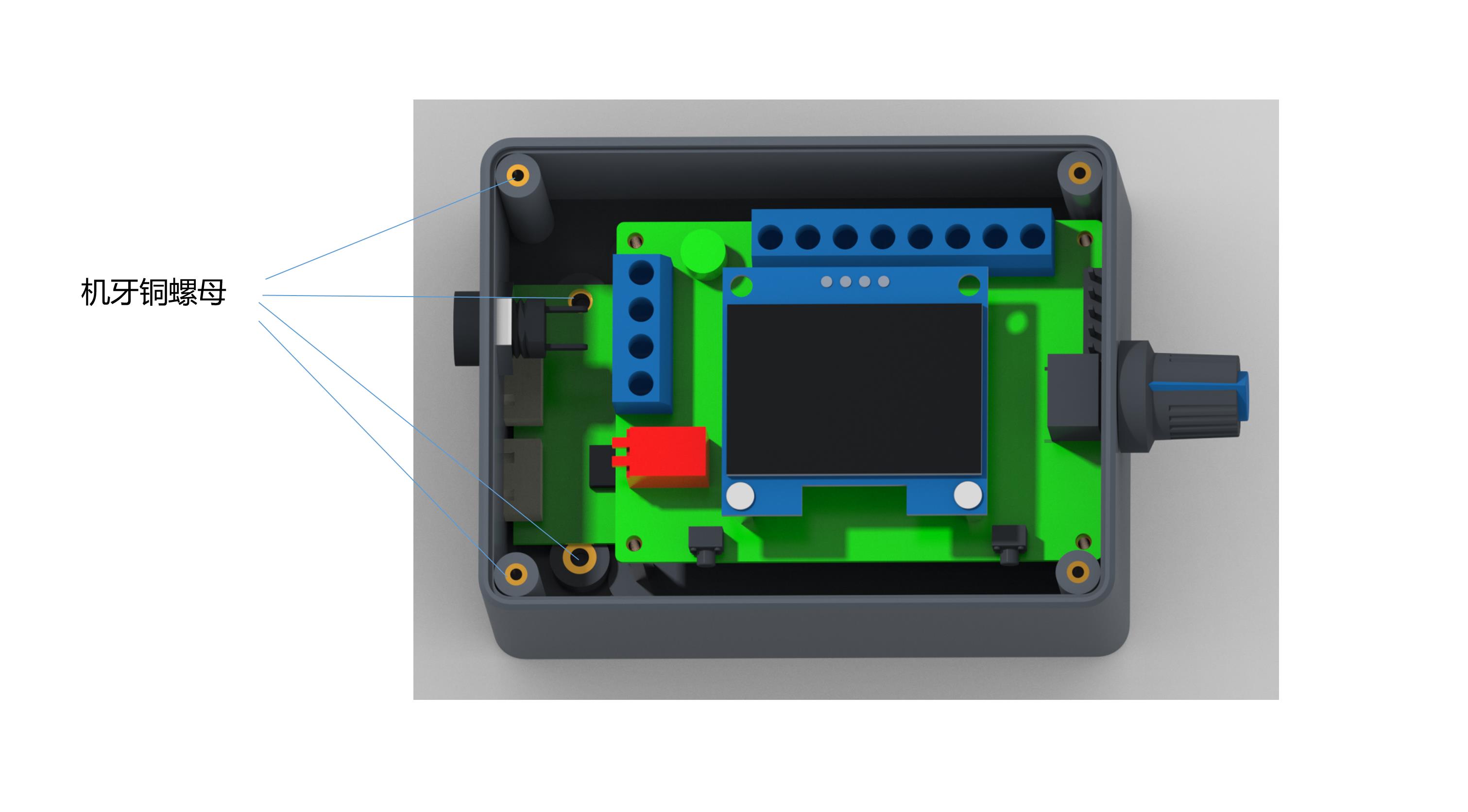
Wiring and Internal Function Description
- Governor/Motor power supply positive input.
- Governor/Motor power input negative.
- Positive output of the motor power supply.
- Negative output of the motor power supply.
- Rotation Control (F/R): High/low level output, controlled by touch switch 2. Default: High (5V).
- Brake Control (BRA): High/low level output, controlled by touch switch 1. Default: High (5V).
- Analog Voltage: 0-5V output for analog voltage speed regulation motors.
- PWM1 Reverse: Speed is inversely proportional to the duty cycle.
- PWM2 Forward: Speed is proportional to the duty cycle.
- Feedback Input: Motor feedback signal input (FG).
Note: FG/FG*3 jumper setting depends on actual motor feedback. No jumper cap = single FG; with jumper cap = 3 times FG*3. The same logic applies to CW/CCW settings.
🛠️
Parameter Settings Guide
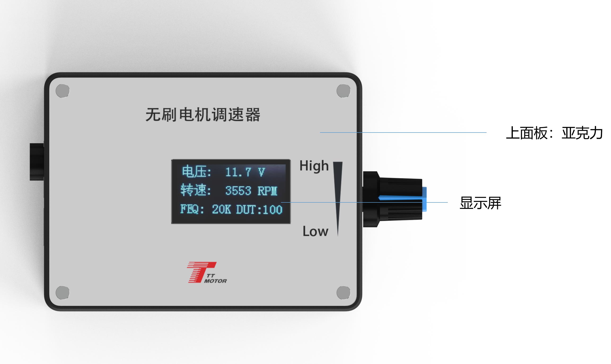
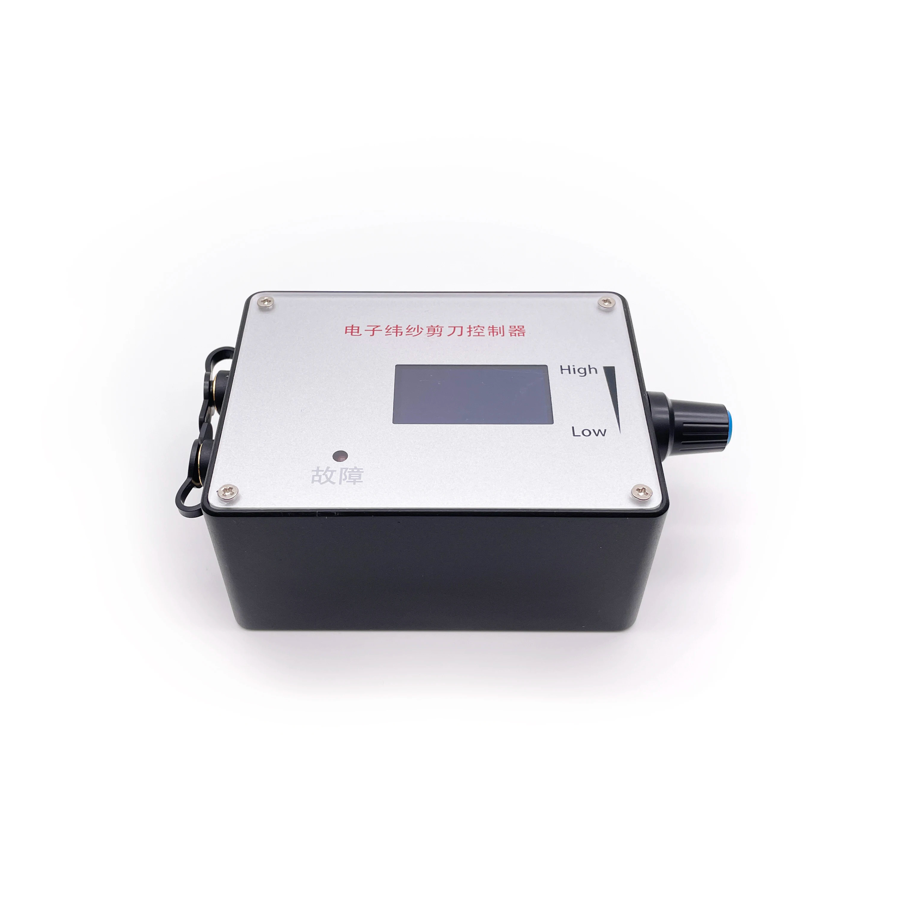
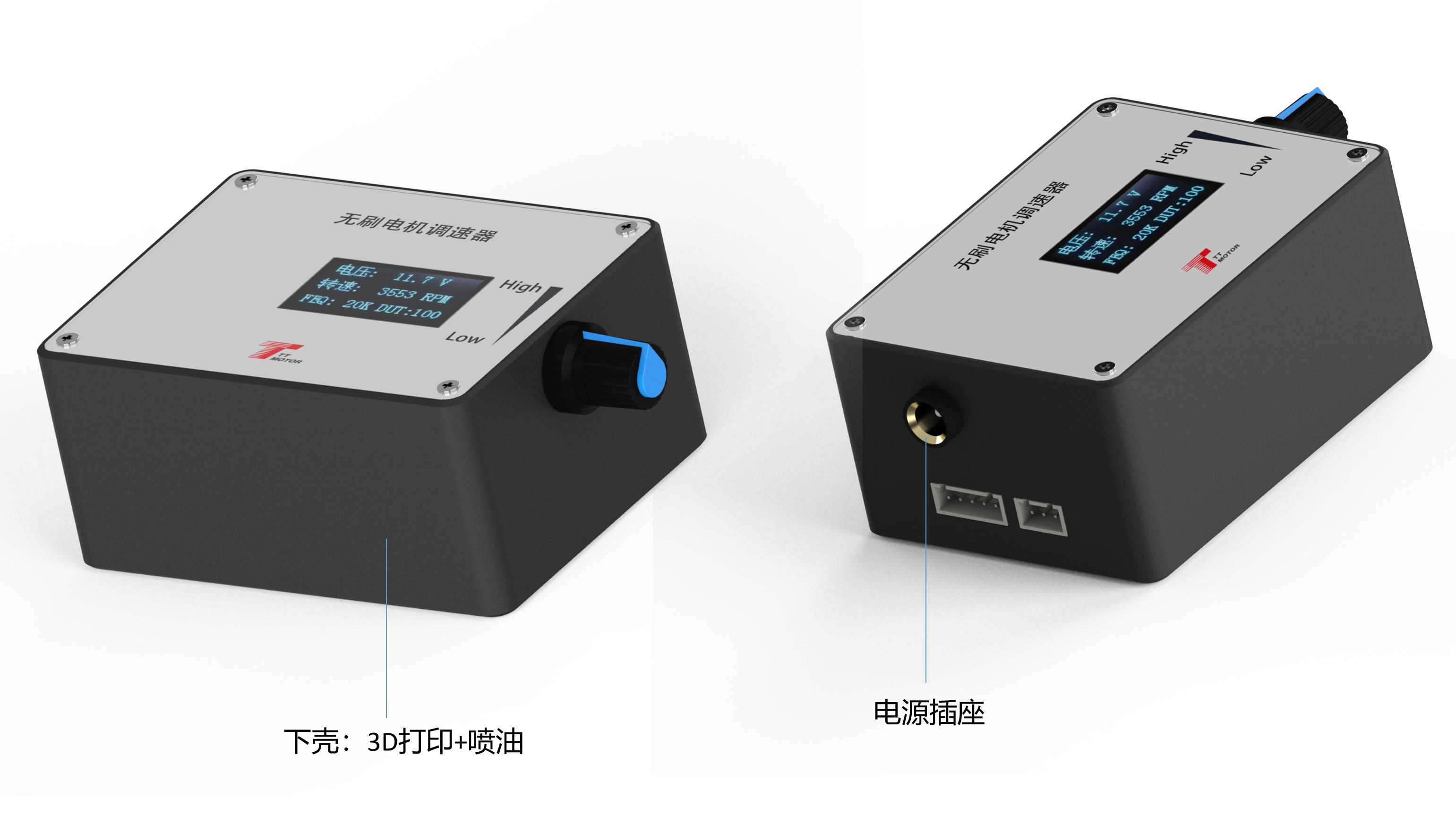
1 Frequency Setting: Press and hold Switch 1 before power-on. Release when "FEQ:20K" appears. Use Switch 1 to reduce and Switch 2 to increase. Default: 20KHz.
2 Number of Poles: Hold Switch 1 and Switch 2 simultaneously before power-on. Release when "Pole Number" appears. Use Switch 1 to reduce and Switch 2 to increase. Default: 1 pole.
3 Feedback/Direction: Use jumper caps on FG/FG*3 pins for feedback multiples and CW/CCW pins for initial direction states.
4 Main Display: The screen monitors input voltage, speed, frequency, and duty cycle. Speed requires correct Pole and FG settings for accuracy.
Frequently Asked Questions
Q1: What is the operating voltage range for this governor?
The governor supports a DC voltage range from 5V to 28V.
Q2: How can I control a motor that requires more than 2A of current?
For motors with higher current requirements, connect the motor's power line directly to the power supply instead of through the governor.
Q3: How do I change the PWM output frequency?
Before powering on, hold touch switch 1. Once "FEQ" is displayed, use switch 1 and 2 to adjust the frequency to your desired setting.
Q4: What is the difference between PWM1 and PWM2 outputs?
PWM1 provides a reverse output where speed is inversely proportional to the duty cycle, while PWM2 provides a forward output proportional to the duty cycle.
Q5: How do I ensure the speed display is accurate?
You must correctly set the motor's pole number and the feedback multiplier (FG/FG*3 jumper) for the screen to display the correct speed.
Q6: What happens if I reverse the power supply polarity?
Reversing the positive and negative power supply connections will prevent the governor from working and will likely cause permanent damage (burn) to the device.
 Fluxon Motor